Features :
Features and Benefits
 Use either external power or power over serial
- Extends RS-232 transmission up to:
• 40 km with single-mode—TCF-90-S
 • 5 km with multi-mode—TCF-90-M
 - Reduces signal interference
- Protects against electrical interference or chemical corrosion
- Compact size
Specifications
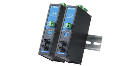
The TCF-90 is a compact media converter that transmits RS-232 signals over optical fiber. Power is derived from either the serial port or an external power source. The TCF-90 extends RS-232 transmission up to 5 km with multi-mode fiber, or up to 40 km with single-mode fiber. A pair of TCF-90 converters can be used to connect two RS-232 devices with optical fiber in full duplex mode. The optical fiber isolates the data signals from dangerous increases in ground potential, ground loops, and electrical EMI/RFI noise, and enhances data security by eliminating the harmful effects of RF radiation and susceptibility to electromagnetic radiation.
Self-powered RS-232 to Optical Fiber
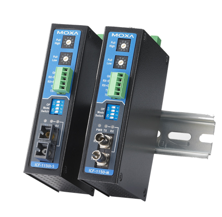
 Connecting RS-232 devices to the TCF-90 is easy. The ST-type optical fiber connector is designed especially for data communication applications that transmit data either between or within buildings. The TCF-90 can be used for industrial applications and for applications that require secure data transfer.
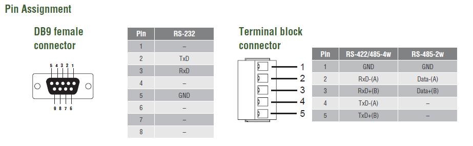
The RS-232 port on the TCF-90 uses a DB9 female socket to connect directly to the host PC, with power drawn from the TxD, RTS, and DTR lines. Although the TCF-90 can obtain enough power from the three data/handshake lines whether the signal is high or low, we strongly recommend setting either the RTS or DTR signal to ON.
LED Port Power Indicator
 It’s easy enough to use a multimeter to test if the serial device is supplying the TCF-90 with enough power through the serial connection, but why bother when the TCF-90 can do the testing for you? Connect the TCF-90 to the device’s RS-232 port and set the SW4 switch to Test mode. If the port power LED indicator lights up, the TCF-90 is receiving enough power. If the LED does NOT light up, you will need to attach an external power source to the TCF-90.
Optional External Power Source
In most circumstances, the TCF-90 should be able to operate without using an external power source. However, an external USB power cord or DC power supply can be used in situations where the handshake lines are not available, both the RTS/DTR signals are set to OFF, or the attached device’s serial interface chip provides less power than required.

Diagram :

Specification :
| • Optical-Fiber Side | |
| Fiber Connector | ST |
| Fiber Cable Requirements |  |
| • RS-232 Side | |
| Connector | DB9 female |
| Signals | RS-232 Tx, Rx, GND (Loop-back wiring: RTS to CTS, DTR to DSR and DCD) |
| Baudrate | 300 bps to 115.2 kbps |
| • Physical Characteristics | |
| Housing | ABS + PC |
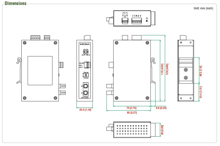
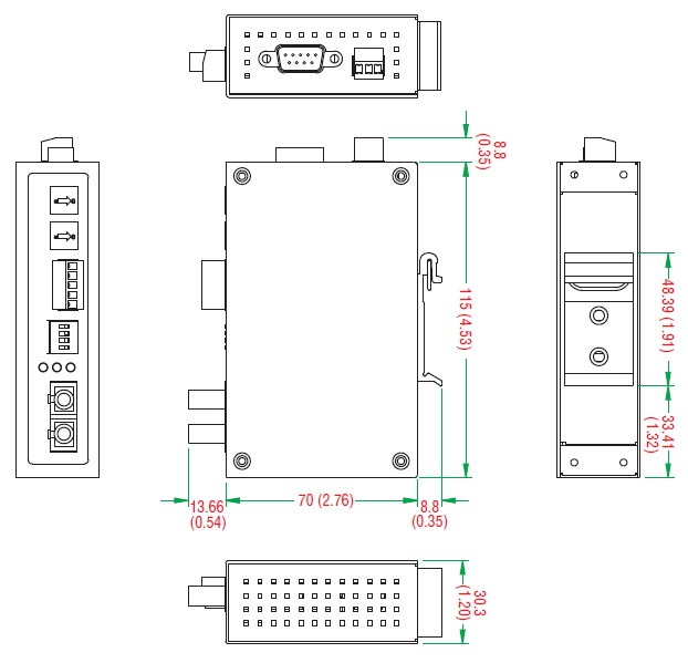
| Dimensions | 42 x 80 x 22 mm (1.65 x 3.15 x 0.87 in) |
| Weight | 150 g (0.33 lb) |
| • Environmental Limits | |
| Operating Temperature | 0 to 60°C (32 to 140°F) |
| Storage Temperature | -20 to 75°C (-4 to 167°F) |
| Ambient Relative Humidity | 5 to 95% (non-condensing) |
| • Power Requirements | |
| Source of Input Power | RS-232 port (TxD, RTS, DTR) or power input jack |
| Input Voltage | 5 to 12 VDC |
| Input Current | 20 mA @ 5 VDC (with termination disabled) |
| • Standards and Certifications | |
| Safety | UL 60950-1 |
| EMC | EN 55032/24 |
| EMI | CISPR 32, FCC Part 15B Class B |
| EMS | EN 61000-4-2 (ESD): Contact: 4 kV; Air: 8 kV EN 61000-4-3 (RS): 80 MHz to 1 GHz: 3 V/m EN 61000-4-4 (EFT): Power: 0.5 kV; Signal: 0.5 kV EN 61000-4-5 (Surge): Power: 2 kV; Signal: 1 kV EN 61000-4-6 (CS): 150 kHz to 80 MHz: 3 V/m EN 61000-4-8 (PFMF) |
| Green Product | RoHS, CRoHS, WEEE |
| • MTBF (mean time between failures) | |
| Time | 2,272,562 hrs |
| Standard | MIL-HDBK-217F |
| • Warranty | |
| Warranty Period | 5 years |
| Details | See www.moxa.com/warranty |


 The TCC-82 provides full electrical isolation for bi-directional serial communication between two RS-232 devices in a compact, industrial-grade package. Both sides of an RS-232 connection are isolated optically to provide perfect protection against lightning surges, accidental high voltage shorts, and ground loops. The built-in, wide range isolators are tested to ensure that they can withstand more than 4 kV rms input to output for 1 minute. This means that the TCC-82 not only meets the requirements of general serial data communications, but also the high standards required by industrial automation and medical applications. The TCC-82 protects the TxD and RxD data lines, and also protects the RTS and CTS handshake lines for a total of 4 isolated channels to provide complete protection of your RS-232 applications.
 The TCC-82 supports port-powered operation, which means that it can obtain power directly from the attached serial devices. Power is obtained from the RS-232 TxD, RTS, or DTR lines, regardless of whether the signal is high or low, eliminating the need for an external power supply. However, external power can be used if handshake lines are not available, if the serial cable is too long, or if the serial device is a low powered device. For external power, the TCC-82 can use a 5 to 12 VDC adaptor or a USB power cord. Note that both sides of the connection are powered independently, so if necessary, one side can rely on port power and the other on an external power source.